Soil Improvement for Liquefaction – New Design Tools to Optimize Your Project

What is Soil Liquefaction and How Modern Geotechnical Engineering Tackles It?

This blog presents the historical context of liquefaction design methods and delves into the mechanics of mitigation. It is particularly relevant as it explores new approaches and design methods for treating difficult-to-improve silty soils and offers a fresh perspective on how to measure these mechanical improvements.

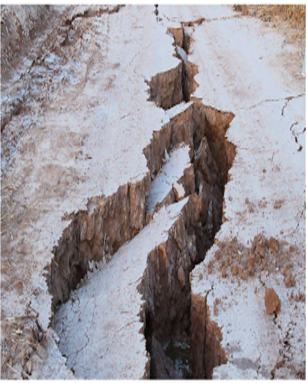
Soil liquefaction occurs when loose, saturated granular deposits close to the surface are subjected to ground seismic movements that are intense and prolonged enough to increase pore pressure. The consequences of liquefaction can be devastating as the reduction in soil shear strength leads to bearing capacity failures, slope instability, large lateral earth pressures, and, subsequently, significant volumetric settlements.

Designing against liquefaction requires an understanding of liquefaction mechanics, knowledge of post-seismic structural requirements, and an understanding of the cost of mitigation measures. Design methods take into account the initiation of liquefaction, the soil’s response post-liquefaction, and the selection of appropriate mitigation methods. These methods can include: avoiding liquefiable strata, reducing shear stresses applied to these strata, or improving the soil to better resist seismic shear stresses.

Traditionally, clean, loose granular soils are improved using methods designed to increase relative density. However, more silty materials, which are also potentially liquefiable, are generally considered less susceptible to densification and often difficult to improve.

Background

Soil liquefaction often has devastating consequences. First identified by Arthur Casagrande to explain static flow failures in earth dams, liquefaction was not a key topic in geotechnical engineering until 1964, when the Good Friday Earthquake in Alaska and the Niigata Earthquake in Japan caused massive ground failures and unprecedented damage. Examples included the catastrophic destruction of port structures in Seward, Whittier, and Valdez, landslides in Anchorage, and the collapse of high-rise buildings and bridges in Japan (National Research Council, 1985).

In 1971, the San Fernando Earthquake near Los Angeles triggered liquefaction-induced instability of the San Fernando Lower Dam. Fortunately, the dam maintained an adequate freeboard after liquefaction-induced settlement to prevent a rupture that would have likely resulted in downstream loss of life (National Research Council, 1985).

In recent years, liquefaction has severely impacted communities in Chile, Turkey, Indonesia, and Ecuador, and caused the destruction of the Central Business District in Christchurch, New Zealand, during the Canterbury earthquake sequence (2010-2011) (Wissmann et al., 2015).

Post-Earthquake Destruction

Lateral Spreading
Building Collapse

Figure 1: Liquefaction-induced damage in the Christchurch earthquake, New Zealand, 2011

Since the late 1960s, liquefaction has been the subject of numerous university studies, resulting in multiple design methods and guidelines for risk reduction. Much of the early work was developed by professors Whitman and Castro at MIT, who promoted methods based on Critical State Theory, and by Professor Seed and his colleagues at Berkeley, who proposed the “simplified method” supported by in-situ testing.

Since then, research has focused on magnitude scaling factors, confinement effects, shear stress impacts, drilling technique effects, the use of Cone Penetration Testing (CPT), and predictions based on shear wave velocity, fines content, reliability analysis, and soil deformation predictions under predominantly geostatic conditions.

Despite the vast amount of work, many uncertainties still exist, particularly regarding design guidelines applicable to geotechnical practice. Examples include:

  • How to easily predict deformations at sites with evidence of liquefaction triggering, loaded by both geostatic and structural stresses? 
  • How to design deep foundations in liquefiable soils, considering potential downdrag effects and lateral resistance reduction during an earthquake? 
  • When and how to apply soil improvement techniques at liquefiable sites, how they work in soils that cannot be easily densified, and how to calculate post-improvement deformations? 

Liquefaction mitigation is of particular interest to geotechnical practitioners because the resulting solutions can involve enormous costs, which are not always scalable to the proposed development.

Since liquefaction originates from seismic loads independent of the structure’s load, solutions that only consider liquefaction triggering, without considering structural response, can lead to inappropriate designs. For example, a site prone to liquefaction and soil distortion may be considered for building:

  • (a) a single-story convenience store, 
  • (b) a 10-story apartment building, or 
  • (c) a 5-story hospital. 

The mitigation solution that limits settlements to 5 cm (2 inches) might be acceptable for the apartment building but inadequate for the hospital (which requires stricter settlement tolerances) and also inappropriate for the store, where the mitigation cost would exceed that of the structure itself.

A Simple History of Design Methods

Liquefaction design is generally developed in three steps for affected sites:

  1. Estimating the liquefaction triggering potential (triggering). 
  2. Estimating the consequences of the liquefaction triggering. 
  3. Determining the most effective method to achieve an acceptable level of performance. 

Liquefaction triggering requires determining both the seismic shear stress applied and the soil’s resistance to rapid increases in pore pressure during cyclic loads. Both aspects usually generate uncertainty, even in experienced geotechnical engineers.

Professor Whitman (MIT) and Professor Seed (Berkeley) were the first to develop a simple method for estimating applied shear stresses using a pseudo-static free-body diagram and simple correction factors. This led to the well-known expression for Cyclic Shear Stress Ratio (CSR):

CSR = 0.65 * amax * σ’v * rd
Where:
τ = applied cyclic shear stress.
amax = maximum ground acceleration as a multiple of gravitational constant g.
σv, σ’v = total and effective vertical stress.
rd = depth correction factor.

The constant 0.65 was determined by Professor Seed to represent the fraction of energy transmitted by high-amplitude wave components, while the factor r adjusts for the non-perfectly rigid response of the soil column.

Soil resistance to liquefaction can be determined using Critical State Theory developed at MIT or, more practically, using the empirical method of Seed and his collaborators. This model, known as Seed’s “Simplified Method,” is preferred due to its ease of application and because it does not require costly sampling or laboratory tests.

Liquefaction Mitigation Methods

Once liquefaction triggering potential, volumetric settlements, and post-liquefaction shear strength are estimated, appropriate design solutions must be developed for the projects.

The most cost-effective solutions typically capitalize on “crusts” of existing or constructed soil layers over liquefiable strata to reduce the effects of liquefaction on the superstructure. In contrast, the more robust (and expensive) solutions generally involve deep foundations designed to withstand downdrag and reduced lateral resistance post-liquefaction.

Soil improvement methods employed to make soils less liquefiable can be based on various mechanisms:

  • Increasing the density of liquefiable layers. 
  • Reducing the applied cyclic shear stresses on these layers. 
  • Increasing drainage to avoid soil instability. 
  • Increasing lateral confinement to allow the soil to resist higher cyclic shear stresses. 
  • Increasing post-liquefaction stiffness of the soil mass. 

Traditional Soil Improvement Methods for Liquefaction

Most traditional soil improvement methods focus on the first mechanism: increasing density, applying vibratory or impact loads to the ground (Figure 4). These include:

  • Deep Dynamic Compaction (DDC) 
  • Rapid Impact Compaction (RIC) 
  • Vibroflotation / Gravel Columns 
  • Rammed Aggregate Piers (RAP) 

These methods are especially effective in clean, loose, saturated granular soils but less effective in soils with a high fines content, as the energy applied dissipates into pore pressure buildup instead of reducing the void ratio and rearranging particles.

Subterranean panels of soil-cement columns, jet grouting, or even tangent piles can also be used due to their higher shear rigidity compared to in-situ soil. However, recent studies (Rayamajhi et al., 2013; Zalachoris et al., 2023) show that individual columns are less effective than expected because they tend to flex (Euler buckling) instead of deforming through shear under load, reducing their effectiveness in overall soil reinforcement.

Conclusion

The research results from Site 3 in Christchurch (New Zealand) show that:

  • In clean sands, both the CPT and shear wave velocity (Go) methods provide consistent results in pre and post-installation conditions. 
  • In the silty sand layer, the CPT method showed no improvement, while the Go1 results showed an increase of approximately 20 to 40% in stiffness. This increase reflects greater soil rigidity due to increased lateral stress, which reduces the void ratio and raises Go1 values. 
  • The increase in Go1 is consistent with the rise in liquefaction resistance due to lateral pressure, as suggested by Amoroso et al. (2024). 
  • The densified clean sand layer between depths of 2 m and 4 m may have been moderately cemented before installation, behaving as non-cemented after RAP installation. 

This research enhances our understanding of liquefaction mitigation in soils classified as “liquefiable but not densifiable” and provides valuable insight into improving soil performance against seismic forces.

By: Kord Wissmann, PhD, PE, BC.GE. Principal, Intechnics, Inc., Mooresville, NC. Allen Bowers, PhD, PE. Chief Engineer, Geopier, a Division of CMC, Davidson, NC. Jorge Arroyo, M.S., PE. Mexico Manager, Geopier, a Division of CMC, Soilsolution

References

  • “Improved Liquefaction Resistance with Rammed Aggregate Piers from Increased Earth Pressure Coefficient and Density.” Journal of Geotechnical and Geoenvironmental Engineering. ASCE, March 2024. 
  • Boulanger, R.W., I.M. Idriss. 2014. “CPT and SPT Based Liquefaction Triggering Procedures.” Report No. UCD/CGM-14/01, Center for Geotechnical Modeling, University of California at Davis. April 2014.
Scroll al inicio